What should a good test specification include?
The answer is simple: it should contain all information that may be necessary during quotation preparation or during design/implementation. It should clearly define the customer’s needs, the expectations on the equipment, and exactly with what (which products, DUTs), what (test steps), and how (sequence of steps, conditions) things need to be done.
A well-written test specification document package not only steers customer communication into the right direction during quotation preparation, but also helps reveal technical risks, approach the technical content in the best possible way, and thus price a solution with the best price/performance ratio. In addition, it can significantly support both the client’s and ProDSP’s work during the design, implementation, and testing phases. On both the customer’s side and ProDSP’s side as the supplier, it minimizes the required resources, reduces project lead time, and maximizes customer satisfaction.
ProDSP is, of course, also open to less complete, less specified tasks, because our goal is to provide our customers with the best possible professional support. In such cases, our colleagues help clarify, concretize, and specify the emerging requirements.
In this article, based on the 20 years of design experience of our colleague István Bogár, we aim to provide answers and guidance on what documents and what information are required during the pricing or implementation of a test tool in order to achieve the goal, as well as to give an overview of the topic of industrial testing.
The Test Tool
ProDSP designs and builds industrial automated test tools, i.e., industrial test equipment and measuring machines. These test tools perform functional (FCT) and EOL (End of Line) testing of the products manufactured by the customer (electrical, mechanical, camera-based measurements) under strictly controlled conditions, in a highly repeatable and documented manner. Based on the obtained test results, the product receives a PASS (compliant) or FAIL (non-compliant) rating, which determines its further fate. By statistically analyzing the information generated during evaluation and recording of conditions, our customers can monitor and improve their manufacturing processes.
The Duality of Function and Form
All of the test tool specifications mentioned above must fundamentally focus on two main topics: function (what and how to test) and form (with what we test and what it should look like). This duality is very similar to the content/form duality often mentioned in artistic analysis.
Function defines the purpose of the device, its “testing capability,” and the product(s) to be tested, while form specifies the structure of the device and parameters beyond core functionality. Therefore, a good documentation package can be divided into the following two topics:
- Test Specification
- Machine Specification
These topics are explained in detail below.
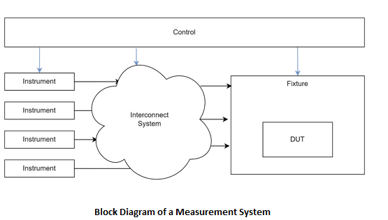
The figure below shows the block diagram of a measurement system implemented in a typical test tool.
Test Specification
The test specification contains all information that clearly describes the primary function of the machine (testing), the device under test (DUT), and the validation of the process.
Device Under Test (DUT)
To understand the testing requirements, it is necessary to properly present the product that is subject to testing. What does the product do, what does it look like physically (pictures, dimensioned and toleranced 2D drawings, 3D model), and how does it connect to the outside world (description of electrical and mechanical interfaces, connectors)? Where can it be gripped or supported and where not, where are the identification labels and 2D codes located, and are there any sensitive points?
Based on this information, the optimal product handling of the test tool can be developed. Mechanically, where does the JIG grip and support the product, and which points must not be covered? Where can the code reader or camera be placed? In what orientation does the product arrive, and how should it be transported further? Is any rotation or movement required at any step? Knowing the mechanical data and interface descriptions makes it possible to design the best possible connections to the product. This includes electrical contact heads and other connection components such as cooling, or any mechanical, optical, and/or RF connections.
For certain non-standard products, it is also important to define additional requirements. For example:
- If the product contains a built-in antenna, where it is located and what its radiation pattern, sensitivity, and radiated power are.
- If hot spots may occur on the product surface during normal operation, how hot they will be and what cooling must be provided.
- If the product requires active cooling, what coolant chemistry and inlet temperature are required.
- If testing the product involves high noise levels, to what extent this noise must be damped.
- If the product radiates RF energy, how isolated the test environment must be.
During the design of the test tool, especially in the case of PCB-level functional testing (FCT), and sometimes even for boxed end-of-line (EOL) testing, it can be very helpful if the circuit diagram of the product is available. Knowing the circuitry of the product makes it possible to select the most suitable measurement instruments or circuit solutions in a way that interferes as little as possible with product operation. Furthermore, the availability of circuit diagrams can save a significant amount of customer communication, thereby reducing customer workload.
An equally important part of presenting the Device Under Test is the description of product variants. How many variants are there, which variants need to be tested, how the variants differ, and how they can be distinguished from one another.
Naturally, any circuit diagrams provided are handled discreetly by our company in accordance with the terms set out in the NDA.
Special Environmental Factors and Requirements
Certain products require a special environment, either because they can only operate properly under such conditions, or because they must be tested under extreme conditions. Such special environments or requirements may include cooling or heating of the product (inverters, chargers), electrical, thermal, or RF isolation, vibration-free environments, or even dark chambers.
Such requirements can also represent significant additional costs, so it is advisable to specify their parameters as precisely as possible and to aim for satisfying them only to the necessary extent.
Cooling
In the case of active liquid or air cooling, it is necessary to determine the amount of power generated/dissipated by the product under test, the allowable temperature range of the product, and the duration of cooling. From this data, the required cooling capacity and the appropriate chiller component can be derived. A significant cost-reducing factor can be whether the production facility has central cooling capacity, because in that case the chiller can be omitted from the test tool and only a cheaper heat exchanger capability is required.
If the cooling agent is a liquid, the need for blowing out the product also arises. After testing, the product’s cooling chamber is still filled with the cooling system liquid, typically a glycol–water mixture. If this material is not removed from the product, it may cause problems in later manufacturing steps. It may contaminate manufacturing equipment, be harmful to operator health, cause electrical short circuits, and not least lead to rapid draining of the cooling circuit. During the blow-out process, the test tool connects high-pressure air to the inlet point of the cooling circuit, which has been emptied as much as possible, and uses it to remove the unwanted liquid from the product’s cooling compartments. This step is almost always indispensable, but it consumes a noticeable amount of time, so it is recommended to account for it when determining cycle time.
In the case of active heating requirements, similar parameters are needed for calculation. If the agent is liquid, the blow-out step is also necessary here, and the cooling of the product back to a handleable temperature must also be considered.
Electrical Insulation
Electrical isolation of the product is also typically a special requirement. By default, the metal components of the machine and the JIGs that contact the product are connected to ground potential. The product’s metal housing, either directly or through ESD-safe (partially conductive) gripping and supporting jaws, will inevitably be galvanically connected to this ground potential. This is necessary in almost all cases, because on the one hand it does not affect test results, and on the other hand it prevents charge buildup and discharge during testing, which could damage the product. However, in certain cases it is necessary to electrically isolate the product from its environment. Such a requirement may arise, for example, during high-voltage testing, where the insulation resistance between certain components of the product (including the enclosure) and the dielectric strength must also be measured.
Radio Frequency Measurements
During radio frequency (RF) measurements, where the test tool examines the product’s RF communication capabilities (e.g., GSM, Wi-Fi, Bluetooth, etc.), an isolated environment is required. Since the manufacturing facility itself and the operators working there also use devices capable of such standard communications, the device under test must be isolated from them during testing to ensure that the instruments measure only the parameters of the product under test. If the test tool is capable of measuring multiple products at the same time, the individual products must also be isolated from each other. When specifying RF isolation, the frequency range and the degree of isolation must be defined, which determines how much of a unit of radiated energy inside the chamber may escape outside. The frequency range and isolation level determine the geometry of the chamber and the type of seals and absorbing materials used. It is advisable to define the minimum isolation value that does not meaningfully disturb the measurement, just sufficient, and then increase this value by a 5–10 dB safety margin based on experience. For such measurements, it is also necessary to specify the type and orientation of the antenna connected to the instruments within the chamber relative to the product. Naturally, the test tool manufacturer can also make recommendations, but the product manufacturer knows the antenna position and radiation pattern within the product more accurately, as the R&D team has likely already created such a test environment during product development.
Other Special Requirements
Additional special environmental factors may include vibration-free test environments or the need to place the product in a dark chamber during certain optical measurements. Many other special requirements may arise during product testing, but in all cases economic considerations must be kept in mind, and therefore parameters should be defined at a level that is just sufficient, supplemented by the previously mentioned safety margin.
Test Steps
Test steps define how the product can be brought into the desired state, how it must be stimulated, which response parameters must be measured, and which ranges of these response parameters are acceptable (PASS) and which are not (FAIL).
It is important that these steps follow each other as logically as possible, because this can save a great deal of cycle time by avoiding the need to bring the product from some base state into the required initial state before each step. Ideally, the product reaches the initial state required for the current step during the previous test step.
Based on our experience, the following sequence is suitable in most cases:
- De-energized measurements:
- Continuity tests to determine isolation of individual components
- Impedance measurements (to verify passive components in the product)
- Safety-related measurements (high-voltage tests)
- Isolation resistance measurements between isolated high- and low-voltage blocks
- Dielectric strength testing between isolated high- and low-voltage blocks
- After high-voltage test steps, it is necessary to insert de-energization steps during which charged capacitances in the device are discharged under controlled conditions, ensuring that the device is not dangerous for the operator or for instruments used in subsequent tests.
- Ground bonding and enclosure grounding verification using high current
- Verification of basic device operation and programming:
- Applying supply voltage, inrush current measurement
- Flashing if required, followed by device reboot
- Device configuration, idle current measurement
- Putting the device into sleep mode, sleep current measurement
- Waking the device and monitoring the current profile of the wake-up process – for this purpose we recommend our DRCM product, which was specifically developed for this measurement: the device is capable of tracking with high sampling rate (500 kSample/sec) and measuring and recording low and high consumption profiles with high accuracy using fast automatic measurement range switching
- Active-state tests, measurement of internal parameters, interface verification, serial number reading, execution of self-tests and evaluation of their results
- Verification of the main functions of the device (e.g., in the case of a battery charger: charging and battery monitoring)
- Performing calibrations (selective excitations, current and voltage measurements, and other parameters required for normal operation). Device reboot may be required.
- Measurement of main function(s) in such a way that preferably only one function operates in a given step, so that results can be sufficiently separated for correct evaluation
- Testing operation under extreme input conditions
- De-energization (similar to high-voltage test steps)
- Coolant removal: if the product had to be cooled during testing, residual coolant must be removed from it as the final test step
From the above list it can be seen that the testing process is fundamentally a series of elementary test steps. To maintain high manufacturing quality, each such elementary step must be specified precisely in the following way:
- Initial state of the product before the test step: exactly what starting state the product must be in before the given test step, and how it can be brought into that state
- Stimulation of product inputs during the test step: every product is inherently connected to its environment, and during operation it responds to stimuli from the outside world with predefined responses. Functional testing verifies whether these responses meet expected behavior. Therefore, stimulation parameters and their allowed tolerances must be specified. Since tests are performed in real physical environments, ideal stimulation parameters can only be approximated with some accuracy. Higher accuracy usually entails higher costs, so a balanced solution is recommended that stimulates the product as accurately and economically as possible. Types of stimulation may include:
- Electrical (power supply, communication signals, output loading)
- Mechanical (orientation, movement, rotation, counterforce, button presses)
- Radio frequency (communication signals, emission, immunity)
- Other (light, temperature, etc.)
- Specification of the product’s response to stimulation: the measurement and evaluation phase of the test step. It must be clearly specified with what accuracy the response must be measured and within which ranges it is acceptable.
Statistical Monitoring of Test Step Results (CPK)
When specifying the test tool, it is important to define the required Cpk value (see: ProDSP blog: Process Capability Index – the key to manufacturing quality), upon achieving which the customer considers the machine’s correct and reliable operation proven. This value can be obtained during the MSA (Measurement System Analysis) process from statistical evaluation of repeated measurements.
It is recommended to record and statistically monitor the results of individual test steps both during test tool validation and later operation. In most cases, these functions are performed by the user’s (factory’s) MES system, but the software running on machines developed by ProDSP Technologies is also capable of this. Based on statistical analysis of measurement results, it can be determined whether the test tool meets expectations—i.e., whether it can reliably and safely distinguish good products from scrap (see ProDSP blog: Validation of Production Line Measurement Systems). If the operator is able to detect short-term changes in statistics and properly analyze the change itself, several useful insights can be derived, such as:
- Drift in product manufacturing parameters (e.g., a different batch of a component is used, affecting product operation in an unexpected way)
- Damage or degradation of the test tool during use (e.g., contaminated probe pins causing poor contact and false failures)
- Incorrect parameter settings of a test step (e.g., good product output values clustering near one limit of the specified range, producing false failures)
In industry, Cp and Cpk (process capability index) indicators are used during test tool and process validation.
- Cp: measures whether the spread of test process results falls within specified limits.
- Cpk: in addition to spread, also indicates how centered the test process results are.
These indicators focus on the capability of a given machine, ignoring process-related effects. Their calculation requires 20–50 consecutive measurements. It is very important that during data collection no changes which do not originate from machine properties occur that affect measurement: no machine downtime, operator change, product change, tool change, or environmental change. This ensures that measured deviations and errors originate from the measurement and the measuring machine. If these indicators exceed a certain threshold, the machine is suitable for testing; if they fall below, repair or modification (instrument replacement, improved contacting, etc.) is required.
Golden Sample
The use of a golden sample is also part of the specification. A golden sample is a product that is identical in structure and function to the products being tested, but has been proven to produce a PASS result in every test step (preferably with values centered within the acceptable range). During operation, the operator uses this sample to inspect and periodically validate the machine.
It is recommended to store the golden sample in a dedicated storage location within the machine, accessible only to the operating engineer. It should be clearly marked with its function (golden sample), serial number (to distinguish it from other golden samples), production date, and production batch.
More details about the golden sample and its application can be found in our blog post: The Importance of the Golden Sample in Measurement System Validation.
Test Tool Specification
The test tool specification essentially complements the test specification described above. The test specification answers the “what?” and “how?” questions, while the test tool specification answers the “with what?” question, together creating the complete picture.
Cycle Time, Testing Time, and Handling Time
These are among the most important parameters of both testing and manufacturing equipment. Cycle time defines the time during which the product and the test machine interact in any way. Testing time defines the time allocated specifically for testing, while handling time defines the total duration of activities outside testing. Thus, for test machines, cycle time is the sum of testing time and handling time.
Time factors can significantly influence the complexity and acquisition cost of a test tool, so special attention should be paid to them. Ultimately, testing and handling time together determine cycle time and thus test tool productivity, which defines how many products the tester can process per year, how often a tested product must leave the test tool, and how frequently a new one must be accepted.
During testing time, the test tool connects to the product, performs the required test steps, then de-energizes and disconnects from it. This is essentially the time the tester spends on its primary activity, distributed among individual test steps.
Handling time covers all other activities outside testing: moving the product from a tray or conveyor into the tester’s working position and then out to the appropriate storage location. At low cycle times (fast testing), this time can become comparable to testing time, so it should be handled with care. In some cases, handling time determines whether the tester is fed and unloaded by an operator or by a robot.
Cycle time requirements should be derived from planned annual production volumes (top-down approach), but cycle time can also be derived from the duration of test steps and handling time (bottom-up approach). If there is a large discrepancy between the two values, the number of test tools must be increased or the number or duration of test steps must be reduced, while considering reasonableness and best possible coverage.
Machine Layout and Structure
Machine layout and structure are determined by multiple requirements, including but not limited to:
- Product parameters (size, weight, special requirements)
- Testing requirements (cycle time)
- Ergonomics
- Occupational health and safety
- Environmental requirements (other production line elements and interfaces)
Heavier, larger, or very light and small products fundamentally affect machine layout. In the former case, a larger, more robust machine must be built that can handle the product adequately and support operator or robot work, typically testing only one product at a time. In the latter case, batch processing should be considered, as individual handling would not be economical.
Testing requirements such as expected cycle time also influence layout. High-productivity, low-cycle-time machines achieve targets mainly through parallelization: handling multiple products simultaneously. However, parallelization and high automation significantly increase machine complexity and acquisition cost. Conversely, if cycle time is long and the main activity dominates handling time, a very simple, highly manual device may suffice, with lower complexity and cost.
Ergonomic considerations also dominate test machine design. Meeting ergonomic requirements usually involves low costs and primarily requires attention from designers, yet it significantly affects productivity during operation. With an ergonomic machine, the operator tires much more slowly during a shift, allowing productivity to remain optimal. From an operator perspective, it is important to specify desired workspace spatial relationships and typical solutions used on other machines in the factory.
The operator may sit or stand at the workspace, depending on the degree of fine motor movement required. It is also important how products and scrap are stored and where they are located. Work organization matters as well—whether the operator runs another machine simultaneously. Proper workspace lighting and visibility and orientation of nests, indicators (displays, lights), and buttons are also important. Ergonomic parameters should be set to work for both shorter and taller operators where possible, and adjustable where not (e.g., flexible monitor mounts). Pallet systems used for product handling and transport can significantly support operator work, but machine design must accommodate them throughout.
Occupational health and safety considerations also serve to protect operator long-term health. Protective distances usually increase machine dimensions, and extraction systems, shielding, and electrically lockable doors further increase complexity. During specification, and indispensably early in design, risk assessment must be performed, defining machine hazard level and applicable standards. We discussed the fundamentals of safe machine manufacturing in detail in another article.
Since testing is almost always part of a multi-step manufacturing process, the test machine must integrate organically with the rest of the production line. For stand-alone machines, size and orientation requirements usually need to be met, while in conveyor-based (in-line) production, the test equipment itself must integrate into the system. Providing the planned production layout and defining mechanical and electrical interfaces of preceding and subsequent machines greatly supports designers and significantly reduces iterations.
Typical Machine Layouts and Their Advantages and Disadvantages
- Rotary table layout:
- Parallel test steps
- High productivity
- Complex system
- In-line layout:
- Low handling time
- High automation
- Integral part of the production line
- Ideal for palletized products and panelized PCBs
- Drawer-based layout:
- Easy expandability and parallelization
- Loss of one drawer reduces productivity but machine remains operational
- Operator typically stands
- Comfortable operator position
- Strongly limited reachable workspace; requires significant assistance (product feeding, storage)
- Suitable for long-term operation
- Seated operator layout:
- Comfortable operator position
- Strongly limited reachable workspace; requires significant assistance
- Suitable for long-term operation
- Standing operator layout:
- Less comfortable operator position
- Operator can manage a large area, enabling independent work
- Suitable for shorter-term operation
Information and images about the above layouts are available on the ProDSP website at the following links:
https://prodsp.hu/en/services/production-line-testers
https://prodsp.hu/en/services/laboratory-test-systems
Feeding the Machine with Products
A current trend we also observe is that test machines are increasingly specified with mixed (operator + robot) or fully robotic feeding (how the product enters and exits the test space). Labor shortages and increasing availability of affordable robots and cobots drive this trend.
For robotic or mixed feeding, the following additions are required:
- Geometric calibratability of the product nest, typically by placing pins around the nest for robot alignment
- Larger space around the nest to accommodate robot grippers
- Higher level of sensing, since control systems rely solely on sensor signals rather than human senses
- Robust, fault-tolerant communication between test equipment and feeding/unloading robots, ensuring synchronization and rapid resynchronization after events such as power loss or emergency stops
- Proper propagation of safety events between robot and test machine (emergency button, cage entry)
- Since robotic arms often require cages or area scanners, operation is usually monitored from the rear. Mixed-feeding machines therefore require either rotatable monitors and UIs or duplicated front and rear UIs.
Considering these factors, it is advisable to consider mixed feeding configurations early in specification for new high-productivity machines, as they can be implemented at relatively low cost and provide greater operational flexibility in the future.
Scrap Handling
Although not always included in the initial specification, integrated scrap storage often becomes a topic later. Products can fail at many points and states during production and testing. While some failures might be repairable, repair is often uneconomical, leading to disposal or destruction. However, due to operator monitoring, production volumes, and in some cases the sensitive nature of products (e.g., car keys), scrap must be collected in a controlled, sensorized manner.
A legtipikusabb megoldás az, hogy ha az adott gépen elbukik a termék, akkor a gép addig nem tekinti befejezettnek az adott ciklust, míg az operátor nem dobja be a selejt terméket egy megfelelő méretű nyílásba. Ekkor a selejt egy olyan csatornába kerül, amiben szenzor vagy szenzorok találhatóak, amiket csak a hulló selejt tud aktiválni, majd a selejt egy, a gépben található zárt ajtók mögötti konténerbe kerül.
A typical solution is that if a product fails, the machine does not complete the cycle until the operator places the scrap product into a dedicated opening. The scrap then enters a channel with sensors activated only by falling scrap and ends up in a locked container accessible only to authorized personnel.
This ensures all failed products are collected in a controlled manner, preventing sensitive items from entering the black market. Proper scrap container design can also allow failed products with expensive components to be stored for later repair.
Test equipment control can also be designed to work with existing or commercially available scrap containers or other storage solutions (e.g., PCBA magazines).
Main Design Parameters
During the quotation phase, or at the latest during early design (concept), all main parameters forming the basis of design must be fixed. Later modifications or machine rebuilds usually incur significant costs.
- General parameters:
- Machine footprint, height, maximum allowable weight, and load distribution
- Factory interfaces (power, air, network, cooling water, etc.)
- Interfaces with preceding and following machines
- Control elements and indicators and their preferred placement
- Placement and interconnection of machine subsystems
- Mechanical parameters of product storage and transport
- Safety zone dimensions and safety interfaces
- Type and placement of product and scrap storage and identification systems
- Preferred operator identification methods
- Test-related parameters:
- Product parameters (dimensions, tolerances, weight, forbidden zones), orientation
- Nest parameters (quantity, surface roughness, support points, clamping force, electrical properties)
- Electrical and other connections to the product
- Power currents and inrush
- Other stimulation methods
- Coolant parameters
- Required isolations
- Communication protocols and message content
- Product identification options and placement (1D, 2D codes)
- Product marking methods and placement
- Other supporting information:
- Customer-supplied hardware components
- Customer-supplied software components
- Applied procedures and supporting materials
Checklist
A checklist is attached to the article to track which information has been provided and what additional information may help ensure smooth and fast quotation or project execution.
We also welcome inquiries with low specification levels, as ProDSP provides technical consulting and specification clarification to support our customers.
Click the “Request Checklist” button and enter your details to access the document.